Line Tools#
Line tools offer the ability to create and edit 2D lines on an image. These 2D lines can be used visualise straight lines and solve lens distortion, and are used as part of the Camera Calibration tool-set.
Toggle Line Lock State#
Toggle line lock state will toggle lock state of the selected line’s attributes, if any of the lines attributes are locked, running this tool will unlock all attributes on the selected lines, and running the tool again will lock all attributes.
Usage:
Select line nodes, or the markers/bundles below a line node.
Run tool.
The selected line node attributes will be toggled between locked and unlocked.
Run this Python command:
import mmSolver.tools.togglelinelock.tool as tool
tool.main()
Subdivide Line#
The Subdivide Line tool is used to add more 2D points (Markers) to an existing Line to define a straight line in an image with lens distortion.
Note
To display a straight line select the mmLineShape shape
node and enable Draw Middle.
Usage:
Select Line or Markers on a Line.
Run tool.
New Markers are created on the Line and selected.
Re-position the created Markers to match a straight line visible in an image plane.
Use Solver UI with Line Markers to solve Lens distortion attributes.
To run the tool, use this Python command:
import mmSolver.tools.subdivideline.tool as tool
tool.main()
Camera Calibration#
The Camera calibration toolset can be used to estimate the position and rotation of a camera using parallel lines in an image - as is common in city-scape or architectural photographs.
No 3D (survey or LIDAR) information of the 3D scene is required, this tool works from a single image only.
Other terms for this “calibration” process is camera “line up”.
Calibration Use Cases#
The tool is very helpful for as an aid for modeling buildings or any other environment that contains a flat rectangular surface.
Calibration Use Cases - One Point Perspective#

Diagram of one point perspective. |

Photograph of one point perspective. |
With 2 parallel lines the image contains one point perspective: also known as one vanishing point.
In this case the tool can estimate the translation and rotation (tilt and pan) of the camera, but a known lens focal length and camera film back must be given - field of view cannot be estimated.
Additional to the one vanishing point, the tool can use a horizon line to estimate the camera roll.
Calibration Use Cases - Two Point Perspective#

Diagram of two point perspective. |

Photograph of two point perspective. |
With 2 sets of perpendicular parallel lines (4 lines all together), will create two point perspective; two vanishing points.
With these extra lines the tool can estimate the camera translation, rotation (tilt, pan, and roll), and lens focal length. The horizon line is not used when two vanishing points are used.
A common type of image with perpendicular lines is a bathroom tiles, or the ground or wall of a room. The tiles, walls or ground do not need to square.
Tool Usage#
Create a Calibration set up with the
mmSolver > Line Tools > Create Camera Calibration Setupmenu.Select the
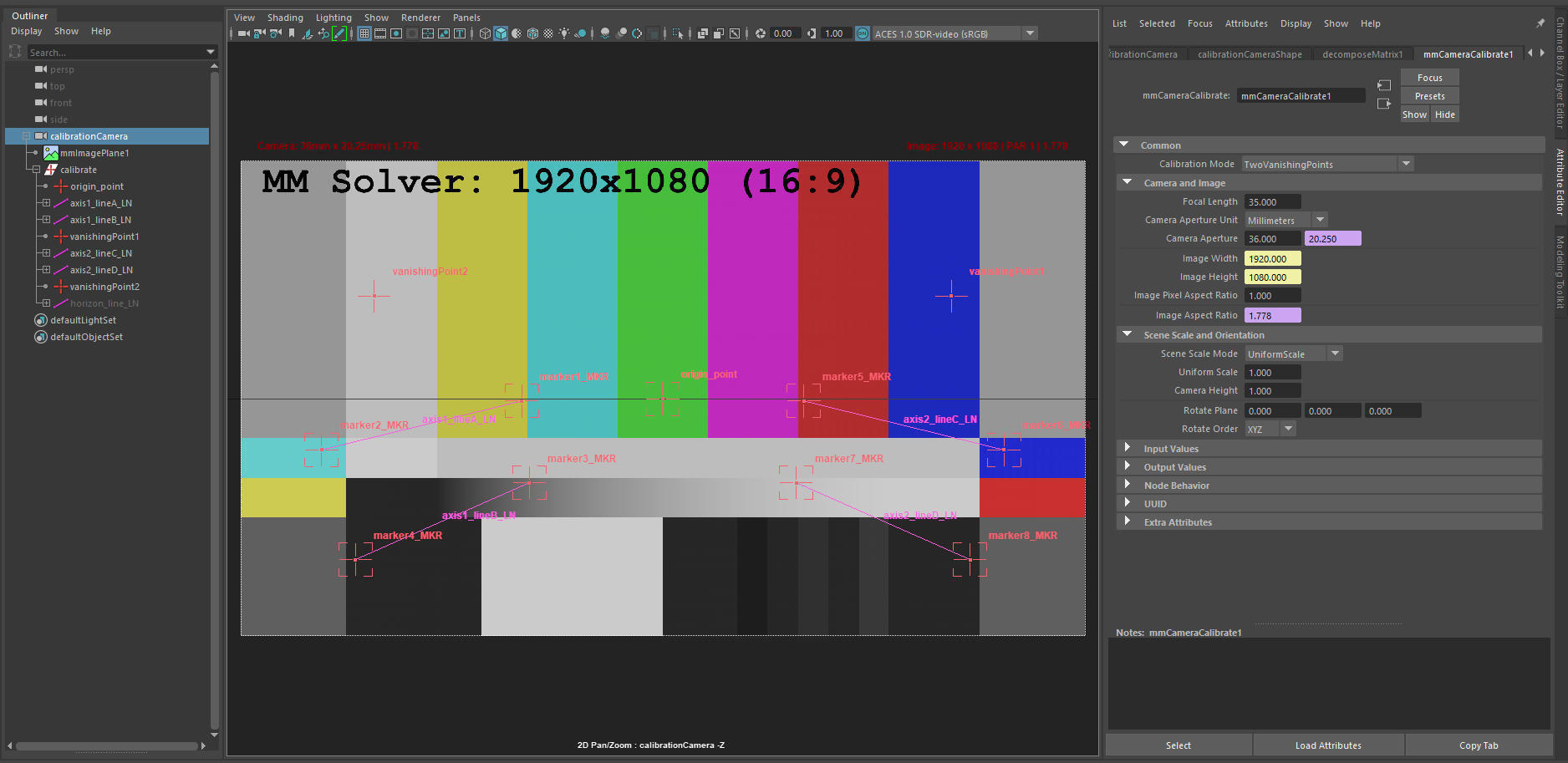
mmImagePlane1node and set the image to point to your image(s). Add image plane file path.Select the
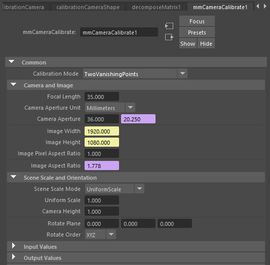
calibrationCameranode, and navigate to themmCameraCalibrate1node - this node is reponsible for calculating the camera translation, rotation, focal length, and film back (camera aperture).Change Calibration Mode depending on how many lines you can see in your image:
OneVanishingPoint,OneVanishingPointAndHorizonorTwoVanishingPoints. See Calibration Use Cases (above) to understand the meaning of vanishing points. This value changes which Axis lines are used to compute the camera calibration and imposes limitations on what can be computed by the tool - for example the Camera focal length cannot be estimated using only 1 vanishing point.Change Camera Aperture width if the value is known.
Change Image Pixel Aspect Ratio to a value other than 1.0 (such as 2.0 or 1.8) depending on the shot/image you are using. For example if your image was captured using an Anamorphic lens and the input image is not “desqueezed” set your pixel aspect ratio here.
Set the lines based on the parallel lines in the shot.
Move the
origin_pointto the intended (2D) origin. This 2D point is where the 3D origin (0.0, 0.0, 0.0) will be placed. For example, place the origin at a corner of a building to make it easier to easily create models that line up with the corner of the building.Select Markers under
axis1_lineA_LNand adjust to align the Line with the a parallel line that is visible in your shot. Repeat foraxis1_lineB_LNso that both lines are aimed along the same axis.If the Calibration Mode is
TwoVanishingPoints, align theaxis2lines as well.If the Calibration Mode is
OneVanishingPointAndHorizon, unhidehorizon_line_LNand set the line to match the horizon line.
“Update” the calibration with the
mmSolver > Line Tools > Update
Camera Calibration
menu to calculate the camera orientation.Repeat steps 3 to 5 until the desired calibration is found.
If the parallel lines in your image are long enough, you can estimate lens distortion values using the following steps.
Select the Line nodes in the Outliner and use the Subdivide Line tool to add more Markers to define the line.
Move the Markers to match the straight edges in your image and repeat by adding more Markers as needed.
Select the camera node in the Outliner and use the Camera Context Menu to add a Lens to the camera.
Then open the Solver UI and add the Lines you want to solve with to the Input Objects.
Select the lens distortion attributes (in the channel box), and add them to the Solver UI Output Attributes.
Switch to the Standard Solver Tab and press Solve.
After the lens distortion is solved, use
mmSolver > Line Tools >
Update Camera Calibration
menu to update the camera again with the straightened lines.
Node Options#
The Camera Calibration tool is driven by the mmCameraCalibrate node and calculates the camera translation, rotation, and focal length. The options below explain how the camera values are calculated using this.
Attribute |
Description |
|---|---|
Calibration Mode |
Controls how the axis lines are used to calculate the camera
calibration. |
Focal Length |
Defines the camera focal length, when |
Camera Aperture |
Defines the camera aperture (film back or sensor size) width. The height is automatically calculated from the loaded image width and height. |
Image Width/Height |
Used to define teh Camera Aperture height and is automatically connected to the MM Image Plane outputs. |
Image Pixel Aspect Ratio |
The pixel aspect ratio of the input image. For example if your image was captured using an Anamorphic lens and the input image is not “desqueezed” set the pixel aspect ratio. |
Scene Scale Mode |
The scale of the computed translation values is can be
calculated with |
Uniform Scale |
When |
Camera Height |
When |
Rotate Plane |
The calculated Camera Calibration can sometimes have a strange axis - for example the camera is upside down. To fix this, use the Rotate Plane to offset the axis values. Use multiples of 90 degrees, or hold-CTRL-middle-mouse-click-drag to shift the values in each X, Y and Z field. |
Calibration Tool Limitations#
This tool has a number of limitations and known issues, and a future version of mmSolver may fix or reduce these issues.
The camera does not yet update automatically while dragging the 2D points.
Only 2 vanishing points (2 sets of parallel lines or 4 lines) can be used.
Some images may require 3 vanishing points, if the center of the lens (“principal point” or “camera film offsets”) is not in the center of the image.
This is fine for most use-cases with (typical) un-cropped images, however issues may arise when a Tilt-Shift lens was used for the image, or the image has been cropped non-uniformly.
If you have this problem it is recommended to use fSpy to calibrate the camera, and maya_fspy to import the camera into Maya.